


Nauja pažangaus valdymo koncepcija: GAZDA G105 + KONLEN
Kaip veikia ši valdymo sistema
Šioje konfigūracijoje KONLEN reguliatorius ir GAZDA G105 sujungti nuosekliai. Tai yra pagrindinis sistemos principas.
KONLEN KL-WT2-T reguliatorius naudojamas kaip pagrindinis patalpos temperatūros reguliatorius. Nors jis turi išorinį temperatūros jutiklį ir gali būti naudojamas vandens temperatūrai valdyti, šioje konfigūracijoje jo jutiklis matuoja oro temperatūrą patalpoje.
Pavyzdžiui, reguliatorių galima nustatyti taip, kad katilas įsijungtų esant 22,1°C ir išsijungtų esant 22,2°C. Vos 0,1°C įjungimo diferencialas leidžia labai tiksliai palaikyti patalpos temperatūrą be didelių temperatūros svyravimų.
GAZDA G-105 reguliatorius atlieka kitą funkciją. Jis stebi šildymo vandens temperatūrą ir daugiausia veikia kaip temperatūros ribotuvas ir saugos reguliatorius. Jei vandens temperatūra pasiekia G-105 nustatytą vertę, katilas išjungiamas, net jei KONLEN reguliatorius vis dar reikalauja šilumos.
Kadangi abu reguliatoriai sujungti nuosekliai, katilas gali veikti tik tada, kai įvykdytos abi sąlygos:
-
patalpos temperatūra yra žemesnė už KONLEN reguliatoriuje nustatytą vertę;
-
šildymo vandens temperatūra yra žemesnė už GAZDA G-105 nustatytą ribą.
Praktiškai KONLEN valdo komforto temperatūrą patalpoje, o GAZDA G-105 riboja didžiausią vandens temperatūrą ir apsaugo šildymo sistemą nuo perkaitimo.
Dėl tokio išdėstymo katilas gali tiesiogiai reaguoti į tikrąją patalpos temperatūrą, išlaikant nepriklausomą vandens temperatūros ribojimą.
Svarbu: KONLEN ir GAZDA G-105 sujungti nuosekliai, o ne lygiagrečiai.
Updated Configuration of Three-Phase GAZDA BE and GAZDA R Boilers (from 2026)
Starting from January 2026, three-phase GAZDA BE and GAZDA R boilers are supplied with an updated control panel configuration.
In addition to the GAZDA G105 temperature controller, the standard setup now includes a 1-module three-phase digital ammeter with three CTs (current transformers).
This applies only to 3×400 V models.
Single-phase KE boilers remain unchanged.
Why current monitoring matters
The power of an electrode boiler directly depends on water conductivity.
Actual current equals actual heat output.
Although tap water in most European countries typically falls within 200–300 µS/cm, real conditions may vary.
The integrated ammeter allows you to:
-
monitor phase current in real time,
-
verify correct boiler load,
-
confirm proper water conductivity during commissioning.
Commissioning reference
After installation, compare the measured current with the reference values in the instruction tables.
If current is too low → conductivity is insufficient.
If current is too high → conductivity is excessive.
If values match → the system operates correctly.
This configuration does not include an energy consumption meter.
It provides essential operational control without unnecessary complexity.

-
GAZDA G105 temperature controller
-
Three-pole circuit breaker
-
Power contactor
-
Three-phase digital ammeter (1 DIN module)
-
Three current transformers (CTs)
-
Circulation pump
-
External room thermostat (optional)
All protective devices and conductor cross-sections must comply with the technical specifications of the specific boiler model.

-
The R series follows the same control logic as the BE series:
-
GAZDA G105 temperature controller
-
Three-pole circuit breaker
-
Power contactor
-
Three-phase digital ammeter (1 DIN module)
-
Three current transformers (CTs)
-
Circulation pump
-
Optional external room thermostat
-
The main difference lies in the internal boiler construction and rated power range.
Electrical control and current monitoring principles remain identical. -
All conductor cross-sections and protective devices must match the specifications of the selected R model.

Wiring diagram of three-phase GAZDA BE electrode boilers with Konlen Wi-Fi thermostat and three-phase ammeter.
In this configuration the heating system is controlled by the Konlen Wi-Fi thermostat (Smart Life / Tuya mobile application), while the three-phase digital ammeter allows monitoring the electrical current on each phase of the boiler.
This wiring configuration applies to the following GAZDA BE models:
-
3 kW
-
6 kW
-
9 kW
-
12 kW
-
15 kW
-
18 kW
-
25 kW
Higher-power BE models use separate wiring configurations.

Wiring diagram of three-phase GAZDA R electrode boilers with Konlen Wi-Fi thermostat and three-phase ammeter.
In this configuration the heating system is controlled by the Konlen Wi-Fi thermostat (Smart Life / Tuya mobile application), while the three-phase digital ammeter allows monitoring the electrical current on each phase of the boiler.
This wiring configuration applies to the following GAZDA R models:
-
3 kW
-
6 kW
-
9 kW
-
12 kW
-
15 kW
In the bottom right corner of the diagram you can also see the electrical terminals used on R-series boilers.
The three terminals L1, L2 and L3 are the phase electrodes, while terminal N is the neutral connection.
These wiring diagrams show how to connect a three-phase electrode boiler — such as the GAZDA BE or R series — controlled by the GAZDA G105 thermostat and a circulation pump.
In fact, the same simple setup works with any three-phase heating device: industrial heaters, electric boilers, or immersion heaters.
The system turns the heater on and off automatically at the set temperature — it’s as uncomplicated as it gets and perfectly suited for reliable daily heating.
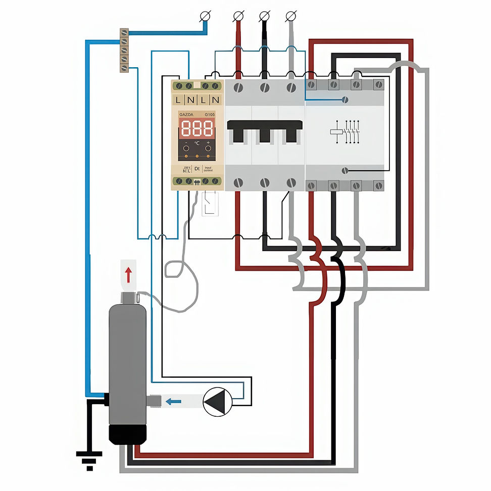
This diagram shows the connection of a three-phase electrode boiler (for example, GAZDA BE series) using the GAZDA G105 thermostat.
It illustrates the main system components, including the 400V power supply, the contactor, the electrical connections, and the circulation pump.
The GAZDA G105 thermostat ensures simple and reliable operation, and also supports the connection of an external room thermostat for more precise temperature control.
Note: This wiring method is suitable not only for GAZDA boilers, but for most three-phase electric boilers and heaters.
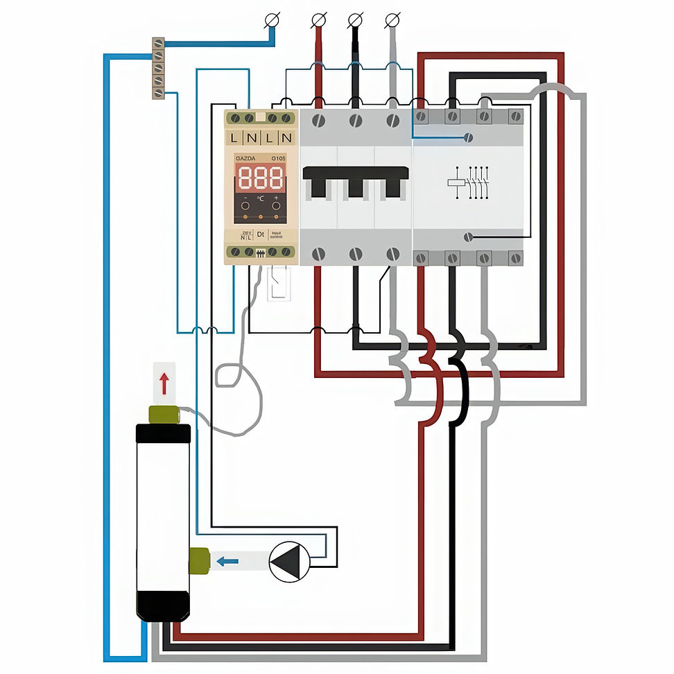
This diagram shows the connection of a GAZDA R series three-phase electrode boiler with the GAZDA G105 thermostat.
It presents the main system components, such as the 400V power supply, contactor, electrical connections, and the circulation pump.
The GAZDA G105 thermostat provides easy operation and supports external room thermostat connection for accurate temperature management.
This scheme can be used for almost any three-phase electric boiler or heater, not just GAZDA series devices.

Wiring diagram for the three-phase GAZDA BE electrode boiler with Konlen WiFi thermostat, without an additional meter.
This solution is for those who want simple and economical control of heating via a mobile app.
No meter means no monitoring of current, voltage, or power, but it gives you a lower cost and maximum simplicity.

Wiring diagram for the three-phase GAZDA R electrode boiler with Konlen WiFi thermostat, without an electrical parameters meter.
All boiler functions are controlled remotely via the app, with no need for extra measuring devices.
An ideal solution if you want savings and easy installation.
Starting from January 2025, we have fully transitioned to using the GAZDA G105 thermostat, which stands out for its simplicity and ease of operation. The new model allows the connection of an external room thermostat, making heating control even more convenient.
Unlike the previous TP-16 model, where users sometimes accidentally switched modes (e.g., from heating to cooling), causing difficulties, the GAZDA G105 is designed for maximum simplicity. The device operates exclusively in heating mode, eliminating the possibility of errors and ensuring stable operation of the heating system.
Below are the updated connection diagrams for the KE and BE and R series boilers.


These diagrams show the wiring of GAZDA KE series single-phase electrode boilers with a capacity of 1-4 kW (first diagram) and 5-8 kW (second diagram). Both configurations use the G-105 thermostat for temperature control and an energy monitor, which not only measures power consumption but also displays current, power, voltage, and other system parameters.
🔹 First diagram (1-4 kW) – suitable for small spaces, private homes, or cottages with a 230V single-phase power supply.
🔹 Second diagram (5-8 kW) – also designed for a 230V single-phase power supply but includes a contactor that supports a higher load compared to the first diagram.
Both systems feature a circulation pump to ensure even heat distribution throughout the heating system. Thanks to their compact design and ease of installation, these boilers are an excellent choice for autonomous heating.

This diagram shows the connection of a GAZDA BE series three-phase boiler using the GAZDA G105 thermostat. It illustrates the main system components, including the electrical connections, the 400V network, and the circulation pump.
The GAZDA G105 thermostat ensures simple and convenient operation, with support for connecting an external room thermostat for more precise temperature control.

This diagram illustrates the connection of a GAZDA R series three-phase boiler using the GAZDA G105 thermostat. Similar to the diagram below, which features the TP-16 thermostat, all key components of the system are represented here as well.
The main difference lies in the fact that the GAZDA G105 offers simpler and more convenient control thanks to its built-in support for connecting an external room thermostat. The plastic housing of the R series boilers eliminates the need for grounding, enhancing electrical safety.
From July 2022, we are equipping all control panels for single-phase and three-phase boilers (Galan and GAZDA) with electricity meters.
In addition to kilowatts consumed, it also displays amperes and volts for each phase, cosφ, etc. All wiring diagrams apply to both Galan and Gazda boilers. The only difference is that single-phase Gazda boilers do not have an earthing terminal, as these boilers are covered with dielectric polymer material and do not need earthing.


This is a simple wiring diagram for single-phase boilers up to 4 kW.
For single-phase boilers of 5 and 6 or 8 kW. It differs from the previous scheme with another (more powerful, up to 63A) magnetic contactor and another main switch (from 25A to 40A).

This is a simple wiring diagram for single-phase GAZDA boilers up to 4 kW.


For single-phase GAZDA boilers of 6 or 8 kW. It differs from the previous scheme with another (more powerful, up to 63A) magnetic contactor and another main switch (from 25A to 40A).

It is the scheme shows how to connect follow-up a temperature regulator air to the existing control unit with a temperature regulator on water. For an example it is represented Computherm q7, but it is possible to use any air temperature regulator.


1-External control device (room thermostat, Wi-Fi relay with potential-free contacts, etc.).
2-Circulation pump
3-Power supply lines
1-External control device (room thermostat, Wi-Fi relay with potential-free contacts, etc.).
2-Circulation pump
3-Control box (overcurrent circuit breaker, meter indicating
current, voltage and current power consumption)
These two wiring diagrams of GAZDA single-phase monoblock boilers GM series. The difference in the two circuits is that the second circuit is supplemented with an electricity meter (in addition to the readings of the energy consumed, there is a possibility of displaying the current and voltage)

Wiring diagram for three-phase boilers such as Geyser 4.5, Geyser 6, Geyser 9, Geyser 12, Geyser 15, Geyser 18 and Volcano 25

Exactly the same wiring diagram as shown above, but with the option of connecting an air thermostat

This scheme for connecting the boiler Vulcan 36

This scheme for connecting the boiler Vulcan 50